This article is free for you and free from outside influence. To keep things this way, we finance it through advertising, ad-free subscriptions, and shopping links. If you purchase using a shopping link, we may earn a commission. Learn more
Precise Parametric Modelling
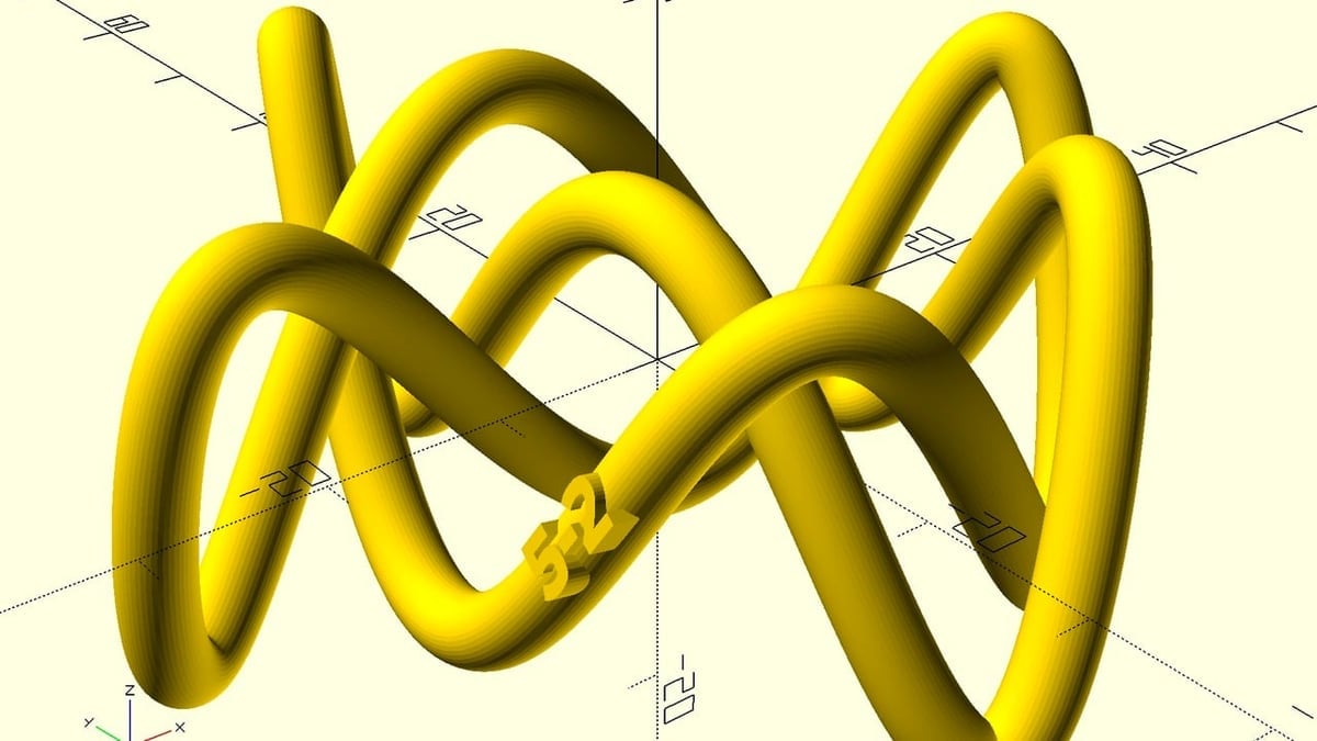
OpenSCAD Tutorial for Beginners: 10 Easy Steps

Check out our OpenSCAD tutorial and quickly learn how to use this powerful 3D CAD modeling tool in 10 easy steps!
Advertisement
Advertisement